Week 12: Output Devices
What should I do this week?
In this twelth week of Fab Academy, there are two types of assigments. The individual assigment is to add an output device to a microcontroller board you've designed and program it to do something.
The group assigment is to measure the power consumption of an output device. Further learnings are listed below:
- Measure the power consumption of an output device
- Read the datasheet for the microcontroller
- Add an output device to a microcontroller board you've designed and program it to do something.
- Explained the programming process used
- Explain the mistakes that I had made and how I corrected it
- Include hero shots of the board
- Link to the group assignment page
- Document the PCB Design and fabrication of the board
- Try out a cool experiments
The following are the softwares that I have used for learning various operations:
- Arduino IDE : Programming
- MIT Mods : Machine Management
Looking back to the previous electronic weeks, I am pretty nervous about whether the PCB routing would go as expected. I am planning to make a DC motor controlled wheel which can be used for robotics projects. As I had combined Week 10 along with Week 12, I plan to use the IR Proximity Sensor as an input device for detecting an object and actuating the DC motor based on data (if possible).
Week 12: Action Plan
| |
|
|---|---|
| Wednesday | Prof. Neil's class on Output Devices |
| Thursday | Designing the circuit |
| Friday | Milling the circuit |
| Saturday | Documentation |
| Sunday | Documentation |
| Monday | Lab closed indefinitely |
| Tuesday | Lab closed indefinitely |
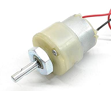
I am pretty sure that I won't be able to complete this week's assigment due the break but I will try to complete it asap. My first agenda is to finish designing the board as soon as possible as the milling and soldering aspect may take time and will depend upon my slot. I had reused the DC geared motor that I had in my inventory, the motor was a 12V unit with 300RPM. This motor can be used in all-terrain robots and variety of robotic applications. These motors have a 3 mm threaded drill hole in the middle of the shaft thus making it simple to connect it to the wheels or any other mechanical assembly. The motor could be controlled using the most popular L298N H-bridge module with onboard voltage regulator motor driver which can support a voltage of between 5 and 35V DC. The geared motor with robust metal gearbox for heavy-duty applications are ideal for robotics and industrial applications.
What is an output device?
An output device is any device used to send data from a computer to another device or user. Most computer data output that is meant for humans is in the form of audio or video. Thus, most output devices used by humans are in these categories. Examples include monitors, projectors, speakers, headphones and printers. Coming the electronic components there are a lot of output devices which include but not limited to servo motor, stepper motor, LCD/OLED Screen, Speaker etc. I am planning to use servo motor for this week's assignment
What is a DC geared motor?
A Direct Current (DC) motor is a rotating electrical device that converts direct current, of electrical energy, into mechanical energy. An Inductor (coil) inside the DC motor produces a magnetic field that creates rotary motion as DC voltage is applied to its terminal. Inside the motor is an iron shaft, wrapped in a coil of wire. This shaft contains two fixed, North and South, magnets on both sides which causes both a repulsive and attractive force, in turn, producing torque. A gear motor is an all-in-one combination of a motor and gearbox. The addition of a gear head to a motor reduces the speed while increasing the torque output. The most important parameters in regards to gear motors are speed (rpm), torque (lb-in) and efficiency (%). In order to select the most suitable gear motor for your application you must first compute the load, speed and torque requirements for your application.
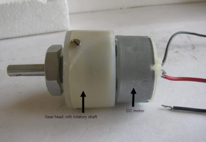
Structure of a DC Motor
At the first sight, the external structure of a DC geared motor looks as a straight expansion over the simple DC ones. The lateral view of the motor shows the outer protrudes of the gear head. A nut is placed near the shaft which helps in mounting the motor to the other parts of the assembly. Also, an internally threaded hole is there on the shaft to allow attachments or extensions such as wheel to be attached to the motor. The rear view of the geared motor is similar to the DC motor and it has two wires soldered to it. the outer body of the gear head is made of high density plastic but it is quite easy to open as only screws are used to attach the outer and the inner structure. The major reason behind this could be to lubricate gear head from time to time. The plastic body has a threading through which nut can be easily mounted and vice versa from the gear head.
Inner Structure
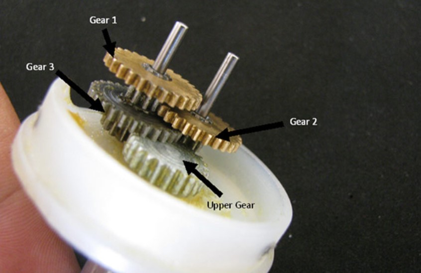
On opening the outer plastic casing of the gear head, gear assemblies on the top as well as on bottom part of the gear head are visible. These gear assemblies are highly lubricated with grease so as to avoid any sort of wear and tear due to frictional forces. Shown below is the top part of the gear head. It is connected to rotating shaft and has one gear that allows the rotation. A strong circular imprint shows the presence of the gear that rotates the gear at the upper portion. The cap that accommodates the gear has an arc cut from its side to avoid frictional resistance forces with the bottom gear assembly. The bottom houses the gear mechanism which is connected to the DC motor through screws. This mechanism rotates the gear at the top which is connected to the rotating shaft. A closer look at the bottom gear assembly shows the structure and connection with other gears. The gear assembly is set up on two metallic cylinders whose working can be called as similar to that of an axle. A total of three gears combine on these two cylinders to form the bottom gear assembly out of which two gears share the same axle while one gear comes in between them and takes a separate axle. The gears are basically in form of a small sprocket but since they are not connected by a chain, they can be termed as duplex gears in terms of a second cog arrangement coaxially over the base. Among the three gears, two are exactly same while the third one is bigger in terms of the number of teeth at the upper layer of the duplex gear. The third gear is connected to the gear at the upper portion of the gear head.
Working of a DC Geared Motor
The DC motor works over a fair range of voltage. The higher the input voltage more is the RPM (rotations per minute) of the motor. For example, if the motor works in the range of 6-12V, it will have the least RPM at 6V and maximum at 12 V. In terms of voltage, we can put the equation as: RPM = K1 * V where, K1 = Induced Voltage,V = Voltage applied. The working of the gears is very interesting to know. It can be explained by the principle of conservation of angular momentum. The gear having smaller radius will cover more RPM than the one with larger radius. However, the larger gear will give more torque to the smaller gear than vice versa. The comparison of angular velocity between input gear (the one that transfers energy) to output gear gives the gear ratio. When multiple gears are connected together, conservation of energy is also followed. The direction in which the other gear rotates is always the opposite of the gear adjacent to it. In any DC motor, RPM and torque are inversely proportional. Hence the gear having more torque will provide a lesser RPM and converse. In a geared DC motor, the concept of pulse width modulation is applied. In a geared DC motor, the gear connecting the motor and the gear head is quite small, hence it transfers more speed to the larger teeth part of the gear head and makes it rotate. The larger part of the gear further turns the smaller duplex part. The small duplex part receives the torque but not the speed from its predecessor which it transfers to larger part of other gear and so on. The third gear’s duplex part has more teeth than others and hence it transfers more torque to the gear that is connected to the shaft.

Designing the PCB using Autodesk Eagle
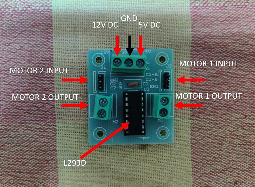
For this week's assigment I had reused the board that I built for Week 10: Input Devices. I had incorporated a 6*2 header pin for the output device week while I had designed the custom board for input devices. The idea here is to control a DC motor using custom board via L293D Motor Driver. L293D Motor Driver Module is a medium power motor driver perfect for driving DC Motors and Stepper Motors. It uses the popular L293 motor driver IC. It can drive 4 DC motors on and off, or drive 2 DC motors with directional and speed control. The driver greatly simplifies and increases the ease with which you may control motors, relays, etc from micro-controllers. It can drive motors up to 36V with a total DC current of up to 600mA. The features of the driver is as follows:
- Wide supply voltage: 4.5 V to 36 V.
- Max supply current: 600 mA per motor.
- The driver two holes of 3 mm dia.
- Male burg-stick connectors for supply, ground, and input connection.
- High noise immunity inputs.
The below image shows the L293D motor driver module that I had used for the project.
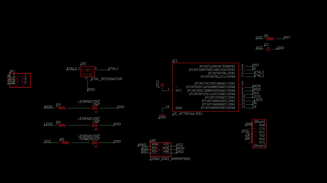
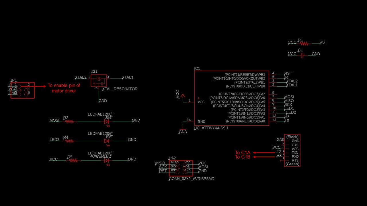
As I had reused the custom board made during Week 10, the schematic remains the same. The motor will be controlled by the custom board powered by Attiny 44 and the DC motor will be connected to it via motor driver. The L293D driver is used as the motor consumes more current which cannot be supplied by the board alone. The schematic of the board is given below:
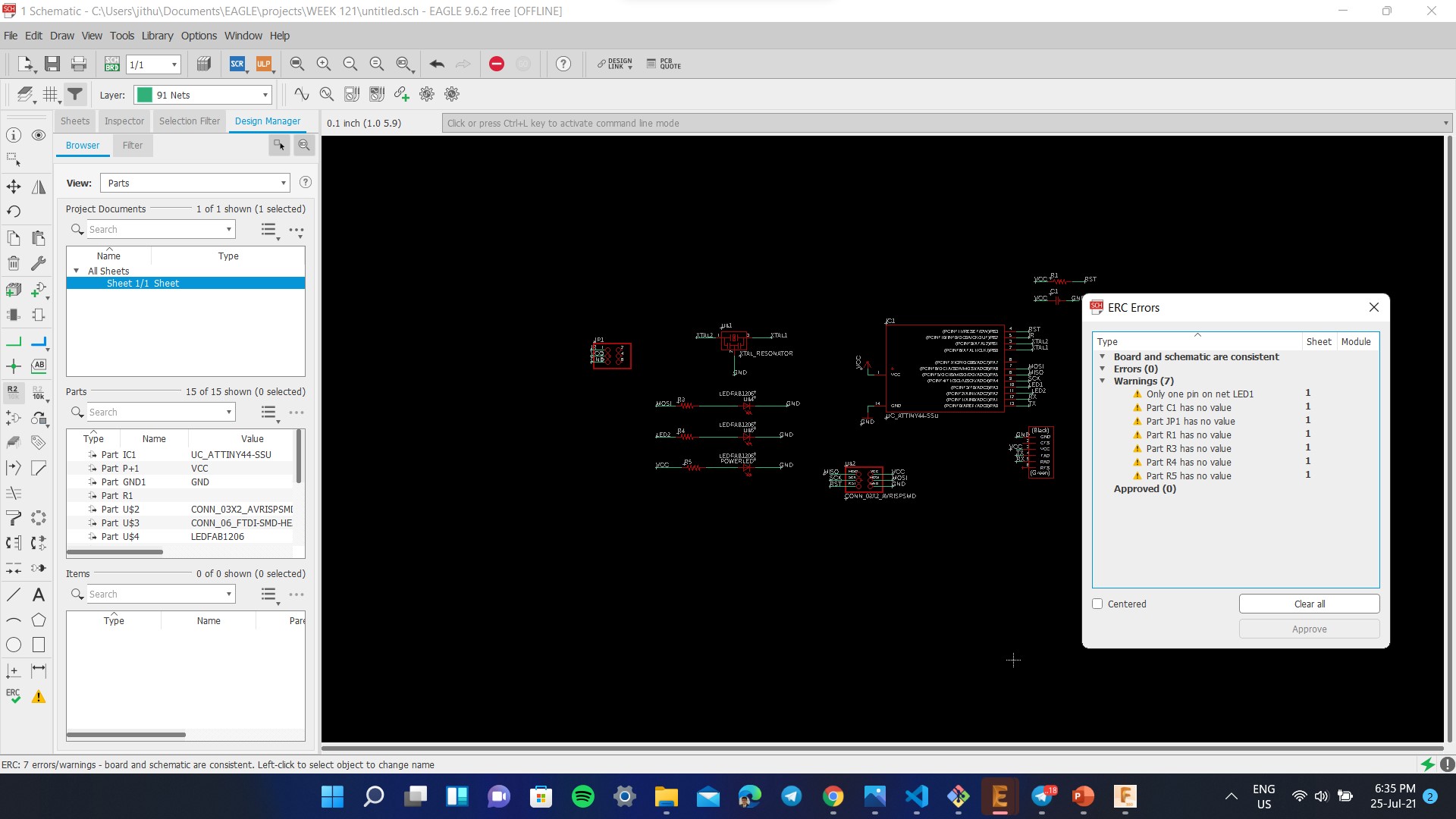
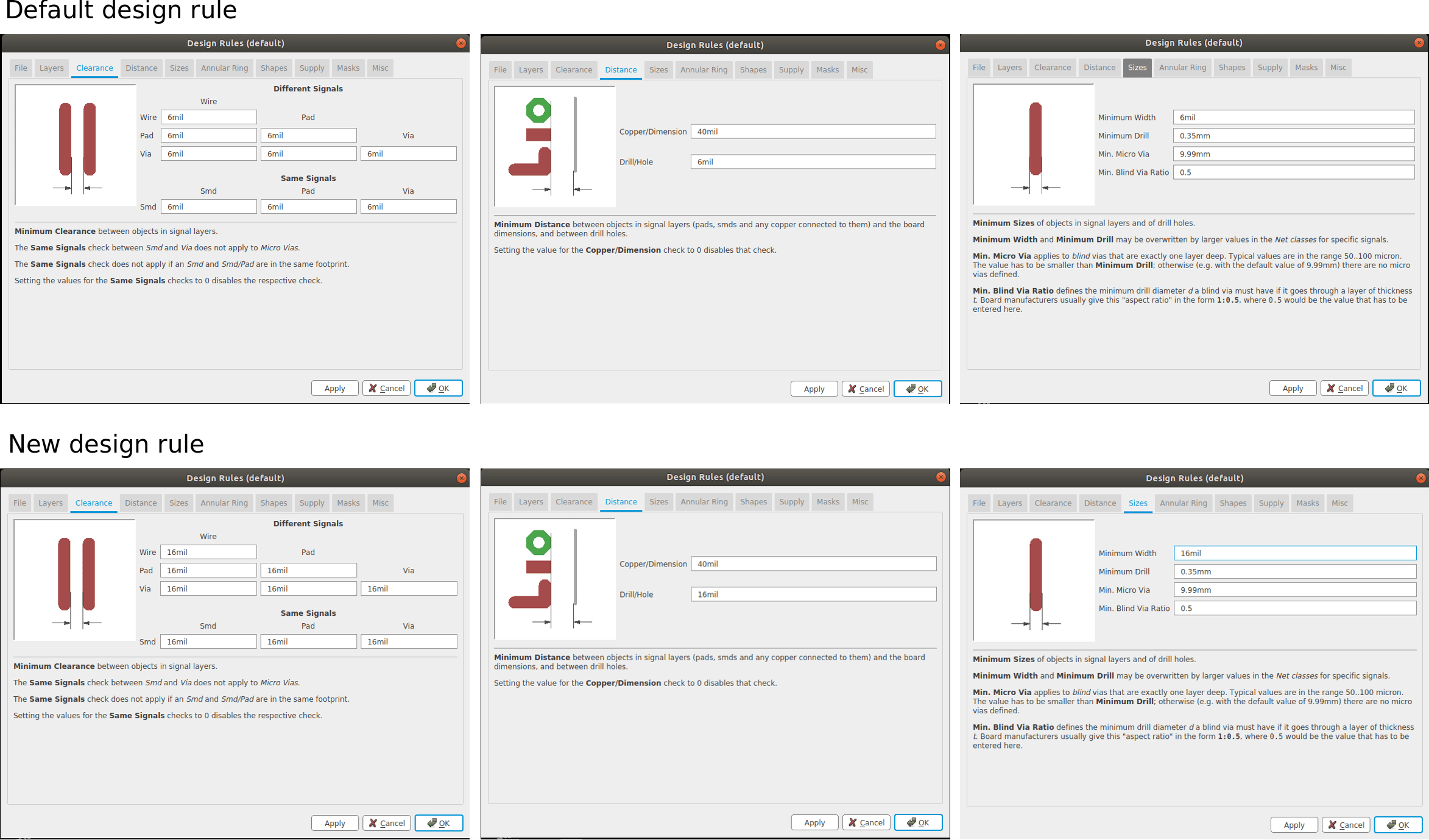
Then you need to place the components away from each other and checked whether the airwires cross each other. You need to rotate and move the components so that there is minimum crossing of airwires. As per the default setting the widths are set to 6mil. This thickness cannot be achieved using our Milling machine. The design rule can be changed from the 'Design Rule' in the 'Edit' option on the taskbar.
For routing the connection I used the 'AUTO ROUTE' tool. Fortunately my biggest fear was busted here, I got 100% routed circuit in my second try and I think this is a huge achivement for me since I now know about placing the components in respective locations to attain the best result.
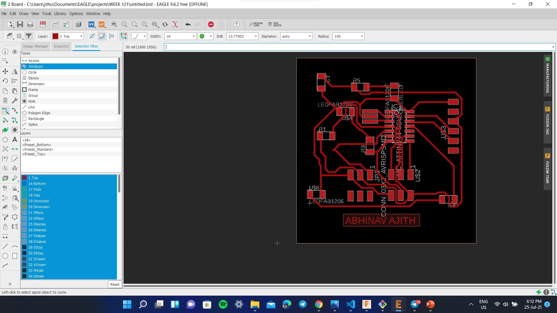
Since I missed this weeks class due to personal reasons, I tried to do this weeks work with Week 12: Output devices as a single board to reduce the machining time. The below image shows the final optimized circuit. The writings on the board design are for our understanding, These writtings must be eliminated before we give it for milling. So for eliminating the writings go to 'LAYERS SETTINGS' and on the 'VISIBLE LAYERS' window enable only the Top layer for the traces.
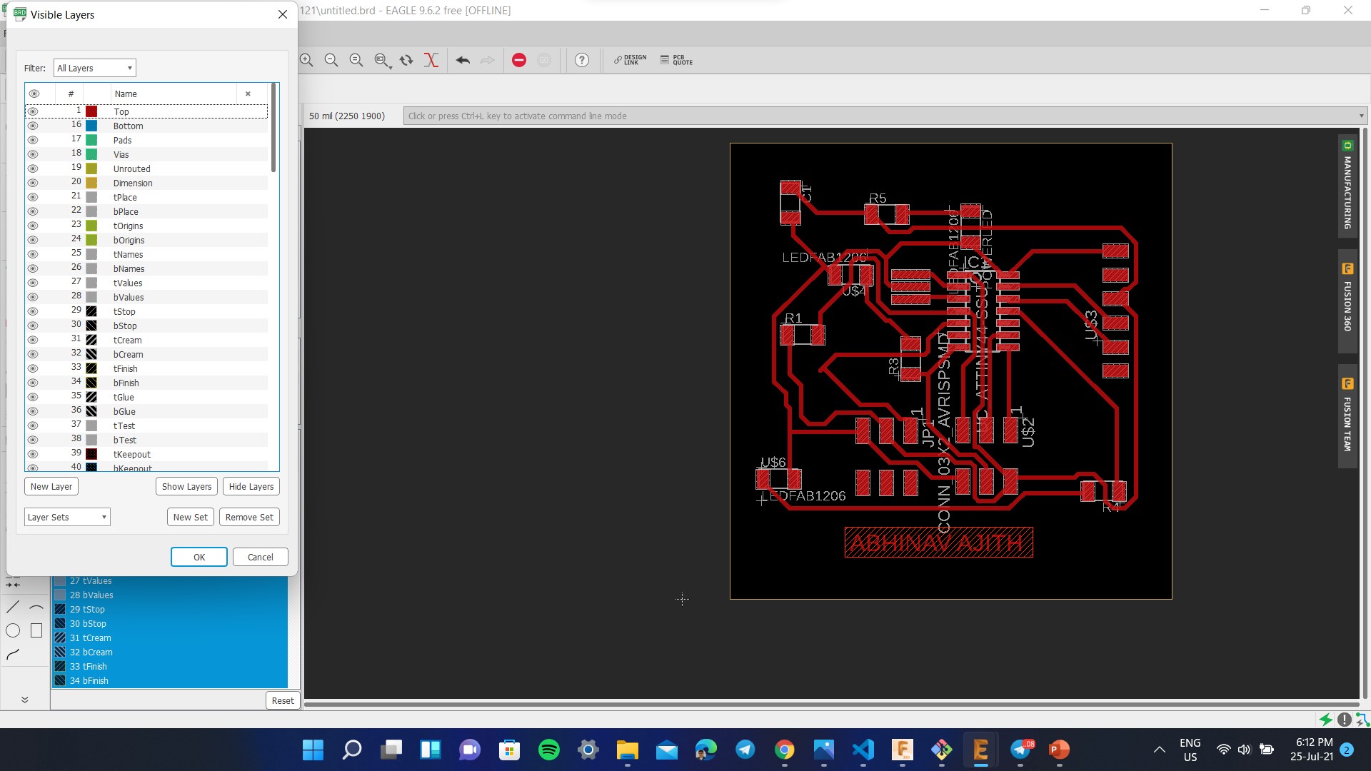
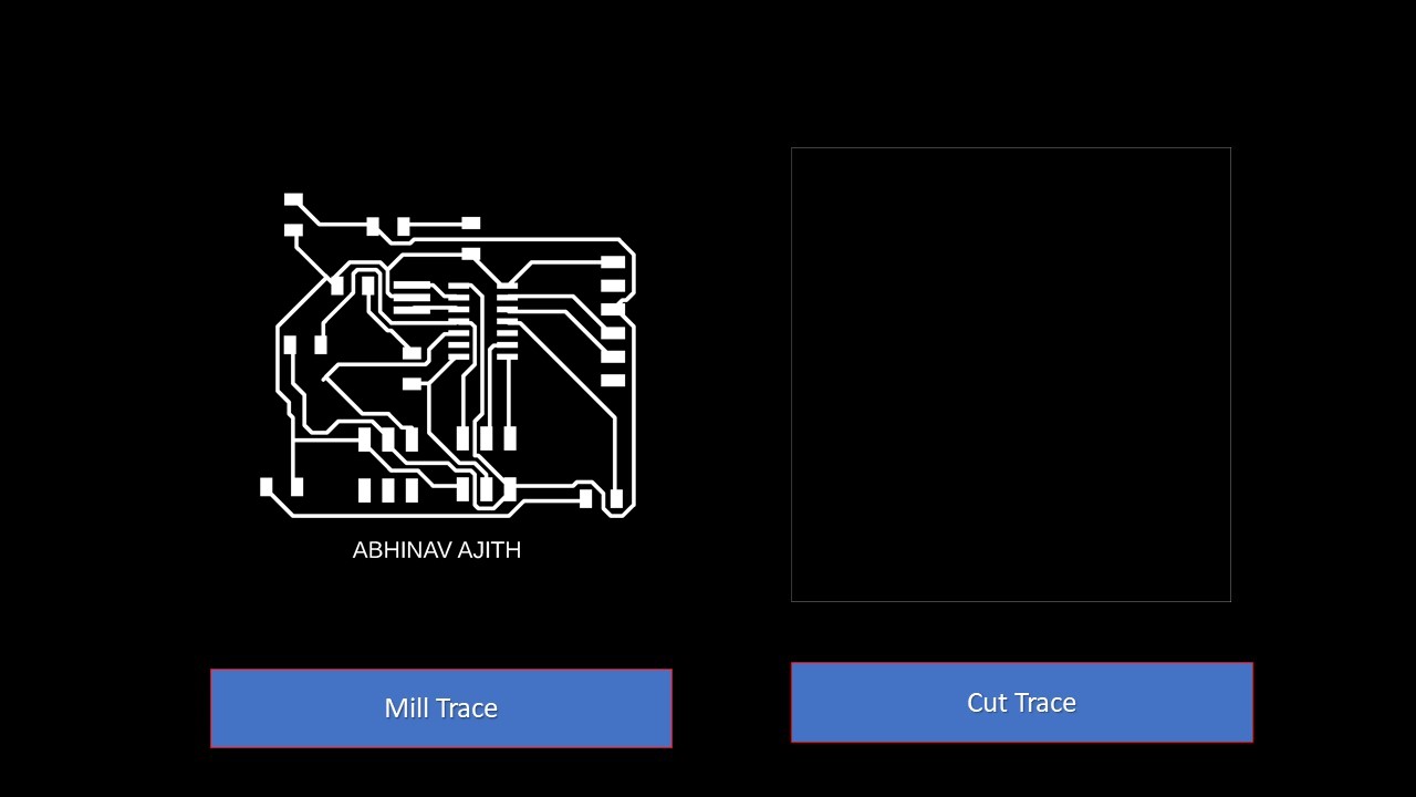
To disable the 'PAD NAMES' and 'SIGNAL NAMES' on the board design, go to 'OPTIONS' on the taskbar and select 'SETTINGS'. On the 'SETTINGS' window click on 'MISC' and disable the PAD NAMES and SINGNAL NAMES. To export the file design as png file, Go to 'FILE' on the taskbar and click 'EXPORT' and select 'IMAGE'. Then a window opens and browse the destination, make it monochrome and change the resolution to 1000dpi. These are the milling and cutting traces of the board
Milling the PCB using Modela PCB Milling Machine
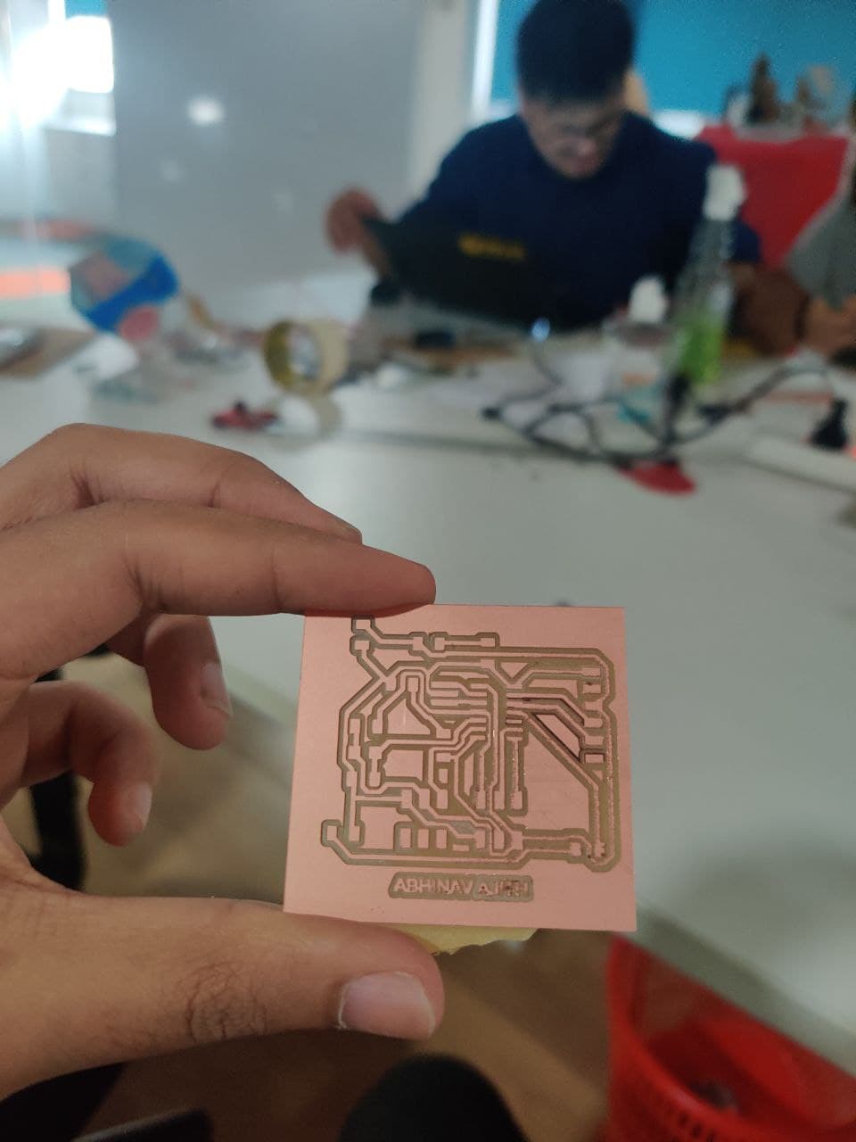
Referring Week 4 you need to export the drawings to the MODS. Always mill out the Traces first using the 1/64 bit and change the tool to 1/32 bit and position the tool to the same origin used for tracing. Afer importing the image you need to calculate the bit and calculate raster. Ensure that you trace first followed by cutting. Once calculation is complete you can verify the tool path by selecting the view command. Next you need to set the origin by going onto suitable coordinates referred from the work area in the milling machine and don't ever forget to remember/screenshot the X & Y coordinates. You can repeat the same process for cutting as well but make sure that you use 1/32 bit and ensure that the origin coordinates are alike. The final step is to verify the origin and to send the file for milling by clicking on send from WebSocket Module. The next step is to clean the board using a vacuum cleaner after completing the whole milling process. Furthermpre, there will be some unwanted copper in the PCB which can be easily removed using a knife. These steps are depicted below
There were some human errors that occured during the milling process. I am listing them below:
- At first the copper was not milled properly, then I troubleshooted and found that the Z axis calibration was not properly done and I also forgot to check whether the surface was bent or not
- The bit went out from the surface of copper during cutting, which was caused due to improper calculation of the area required for the PCB
The next step is to list out all the components required for the project. The bill of components are as follows:
- ATtiny 44 - 1
- XTAL 20 KHz Resonator - 1
- IR Proximity Sensor Module - 1
- ISP Header (3*2) - 2
- FTDI Header - 1
- 10K Ohm Resistor - 2
- 499 Ohm Resistor - 3
- LED - 3
- 1 Micro Farad Capacitor - 1
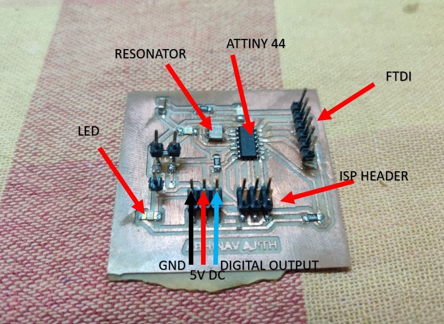
The next step is to solder the components and test whether the board works or not. I had added excess male pins to test out other output pins. The image of soldered PCB is shown below:
There were lot of errors that arouse after the completion of the board. The main issue was with the quality of jumper wire that I had and it had created a lot of unncessary errors which was finally found out and solved. Furthermore proper cleaning of the board was required for perfect operation. The below image shows the connection to the L293D Motor Driver
Programming
For programming, I connected the custom board to the motor driver. The motor driver was then connected to the DC motor. The following code was used
        int in1 = PA0;
        int in2 = PA1;


        void setup() {
          pinMode(in1, OUTPUT); //IN1
          pinMode(in2, OUTPUT); //IN2
           pinMode(PA7, OUTPUT); //ENABLE PIN
        }

        void loop() {

          digitalWrite(PA7, HIGH);
          //FORWARD
          digitalWrite(in1, HIGH);
          digitalWrite(in2, LOW);
          delay(2000);
          digitalWrite(in1, LOW);
          delay(1000);

        //REVERSE
          digitalWrite(in1, LOW);
          digitalWrite(in2, HIGH);
          delay(2000);
          digitalWrite(in2, LOW);
          delay(1000);
          digitalWrite(PA7, LOW);

        }
The code worked as expected and I am adding the video of motor working. The logic of the code is to run the motor in forward direction and then to reverse the direction. This time to code worked successfully and the direction control can be seen in the video.
Group Project
For this week's group assignment, the idea is to measure the power consumption of an output device. We know that Electric power is the rate, per unit time, at which electrical energy is transferred by an electric circuit. The SI unit of power is the watt (W), one joule per second. For measuring power we need, Volatage, Current and Resistance. The equations of power are:
- P=V*I
- P=I*I*R
- P=(V*V)/R
Measuring Power
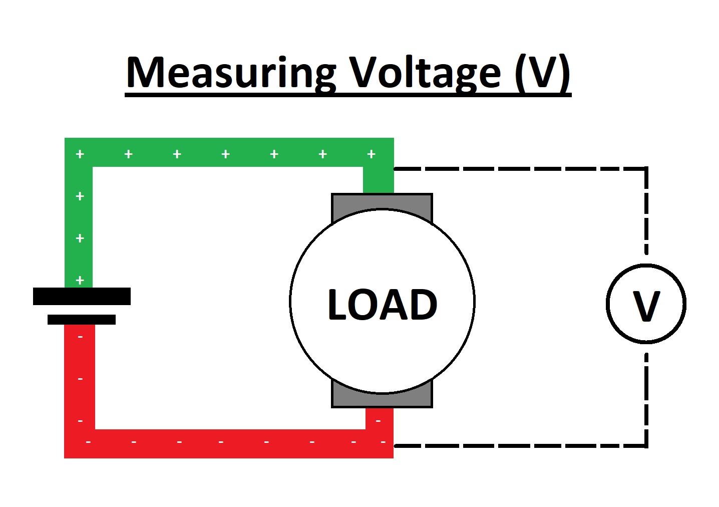
Volage is calculated by connecting parallel to the "Load". Here Units of Voltage is "Volt(V)"
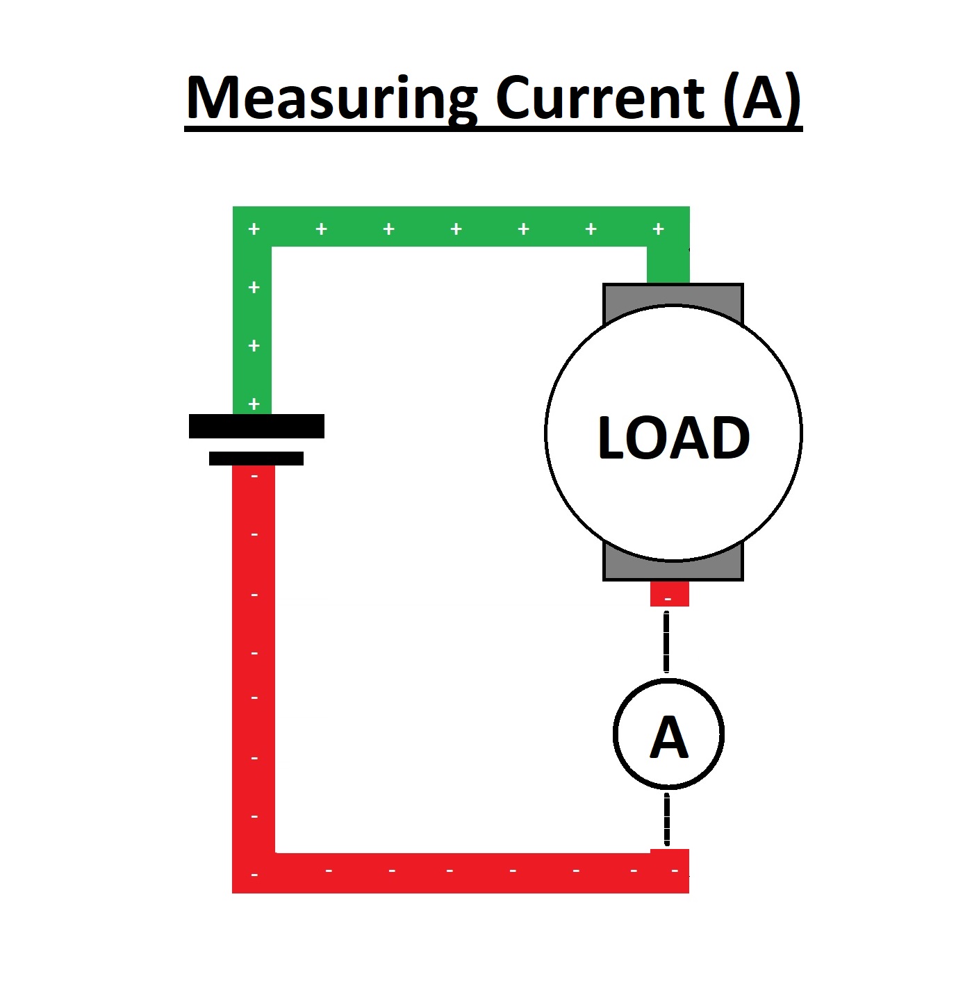
The Current is calculated by connecting series to the "Load".Here Units of Current is "Ampere(A)"
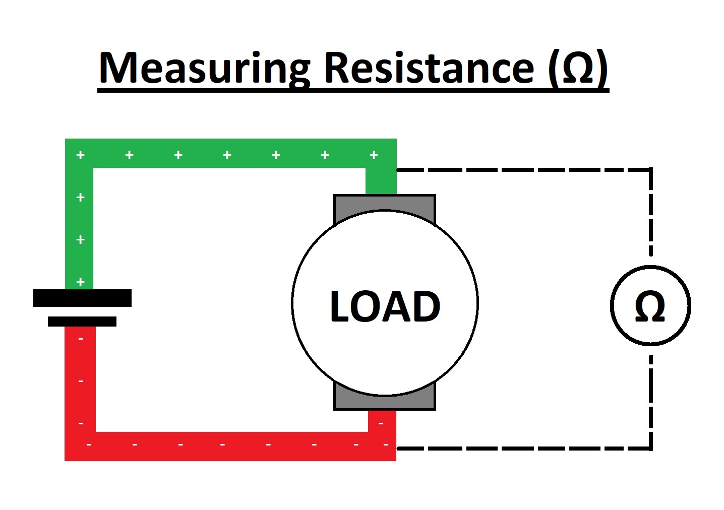
The Resistance is calculated by connecting parallel to the "Load"Here Units of Resistance is "Ohm(Ω)".
I had used 2- 5mm Clear Red DIP LEDs in series to meaasure the current and voltage where I connected it to the VCC and GND of IR Sensor pin. I had used 2 LEDs inorder to avoid the burnout of using a single one. Since I was alone, I had to complete the group project seperately. I had used multimeter to calculate the values
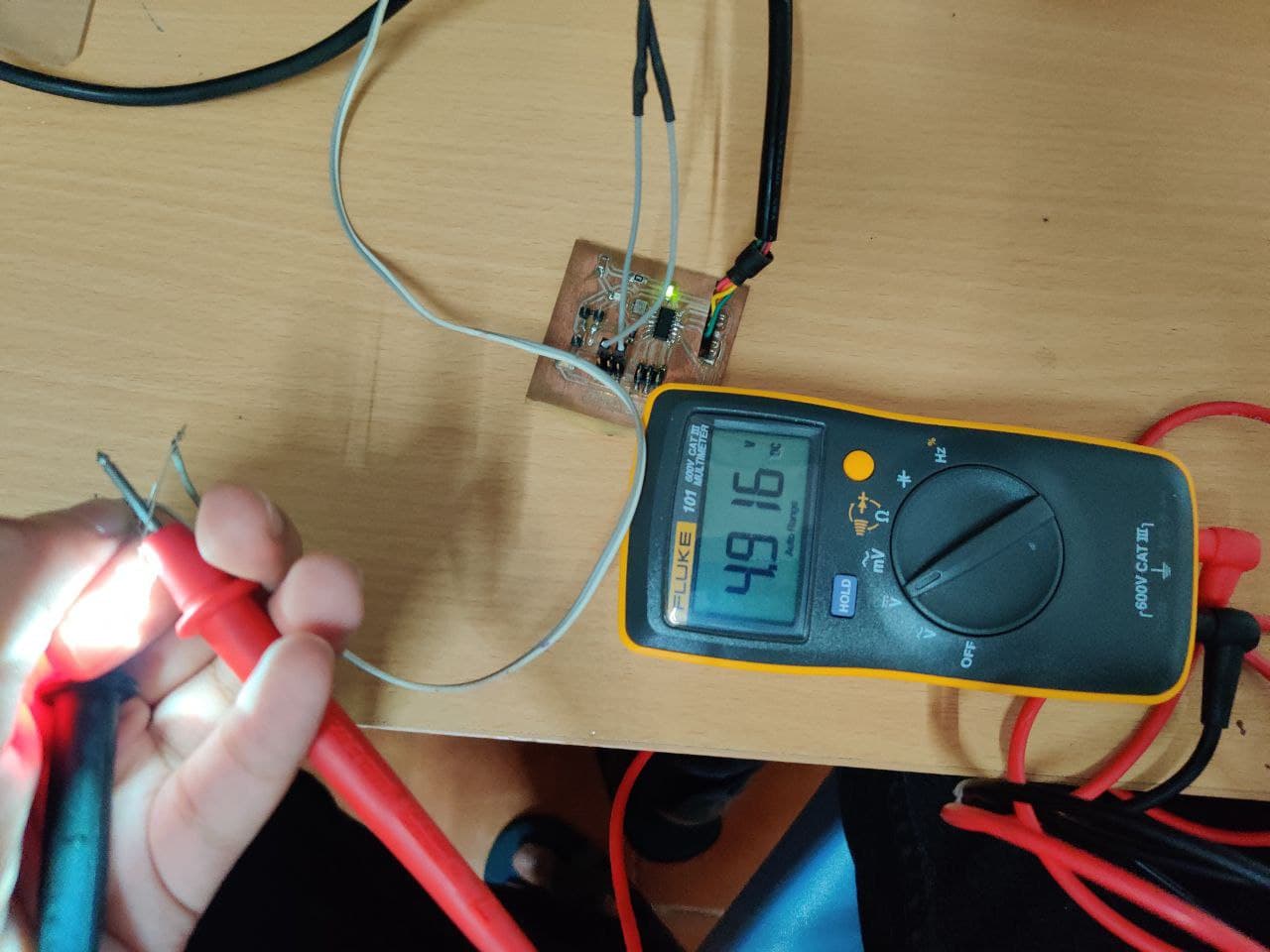
These are the values that I had got when I tested the power consumption of 2 LEDs connected in series. I had also added 33 Ohm resistor to preventt the damage to the board.
V = 5 voltage
I = 30 milli Ampere
So Power = VI, ie 5 * 0.03 = 0.15W
So the power of the output device is "0.25W". By repeating the process and we can find other output devices power consumption.